BUILDING A MODEL
of
THE SWEDISH ROYAL WARSHIP WASA
FROM SCRATCH
by CLAYTON JOHNSON
1/50
1
First and foremost, in order to build my Wasa model, I had to do some research. I contacted Vasamuseet in Sweden and was promptly referred to Fred Hocker, director of research at the museum.
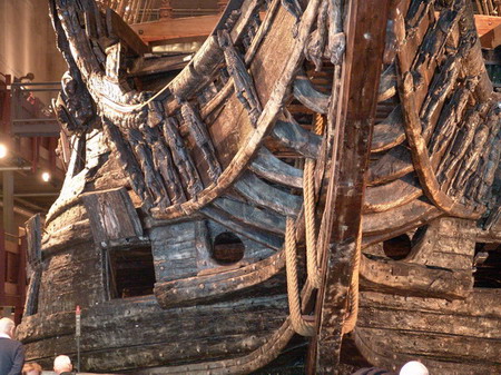
I told him that I wanted to build a model of Wasa with a fully framed hull as the original was built. He told me that since most of the planking on the real ship has never been removed, we do not know where most framing members sit.
Also, the king of Sweden in Wasas time, Gustavus Adolphus, hired Dutch master shipbuilders to oversee the work on Wasa. Their method of shipbuilding required that planking be attached to the keel, stem and sternpost before framing members were laid in. This made it so that there was no incentive to keep framing members square to the keel, as long as there were good overlaps between the parts of each frame.
2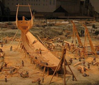
The Dutch method of shipbuilding from a diorama in Vasamuseet.
Because of the fact that the planking had never been removed and the method in which the ship was built, it became clear that it would be impossible to frame my model exactly how Wasa was framed. I had to come up with an approximation.
3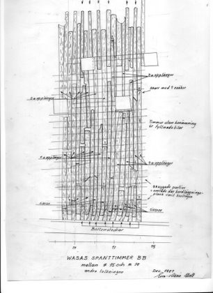
Image Courtesy of Statens Maritima Museer and drawn by Eva Marie Stolt.
A diagram showing some known locations of framing members in Wasa. Notice that it is disorderly due to the Dutch method of shipbuilding.
Fred told me that even though the framing in Wasa is disorderly due to the method in which the ship was built, there is a general pattern to it :
"At a typical frame station, there is a floor timber that reaches the turn of the bilge on each side, a first futtock that reaches from the garboard to a little above the orlop, a second futtock from the head of the floor timber to about the level of the upper gundeck ports, and a toptimber from the upper limit of the lower gundeck to the rail. There are a few filling pieces used in the way of the gunports where it was necessary to cut frames. The ends of the first futtocks are very uneven, as are the upper ends of the second futtocks and the lower ends of the top timbers. In addition, the frames are not square to the keel, but are slightly skewed, and toward the ends of the ship they tend to lean inward, toward amidships. Because the framing is fitted to the planking, rather than the other way round, there was no need to make sure that the frames stood square to the keel and parallel to each other, only that they filled the space and had good overlaps between elements. There are no cant frames at the stern, and the bow is framed in the Dutch manner. Instead of cant frames, the floor timbers continue up the inner face of the stem, normal to the curve, with futtocks stepped on their forward faces. The hawse pieces, which are massive timbers over a meter in width, are butted against the uppermost floor timber, and there are a couple of framing elements parallel to them, filling the space between the hawse pieces and the forwardmost futtocks of the floor timbers."
After receiving this information and after reading a couple of articles, I was on my way to starting my own home-made draws of what would become the framing of my model.
4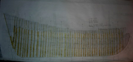
My Framing diagram that approximates the hull framing in Wasa.
I also wanted to come up with frame tracings so that the width of each frame would end up being realistic and they wouldn’t end up too thick or thin.
5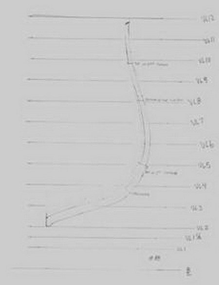
An example of one of my frame tracings. In all there are over 90 frames in my model. Each frame had a tracing drawn of it.
For more information on how I came up with my framing drawings see this website :
http://clayton707.googlepages.com/frameloftingpracticum-research
6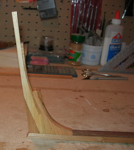
 7
7
Building the keel, stem and sternpost. Materials used in these parts include Cherry, Walnut, Basswood, and Birch.
I use polyurethane on all of the parts in my model. It gives it a nice finish and seals the pores of the wood. This minimizes the movement of the wood due to changes in humidity.
After the keel, stem and sternpost were cut out and assembled, I could now cut out each paper frame tracing, produce billets that were the right thickness for each framing member, and trace the framing member out on the billet. I cut the framing members out with my scroll saw. Each frame has 8 framing members.
8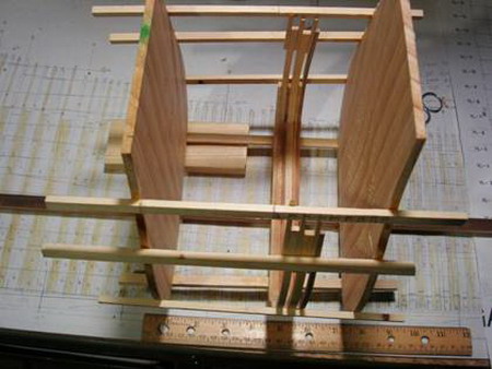
My version of the Charles Davis method.
I used a version of the Charles Davis method of framing that he outlines in his book “The Built up Ship Model”. It essentially involves using upright molds cut to the shape of the hull at each hull station line. I first set up two of these molds, made sure they were straight up and down and square to the keel. I then glued lath between them so that the outside of each frame, when snug up against the lath, would be at the right place. In this way the frames were controlled and would form the shape of the hull accurately.
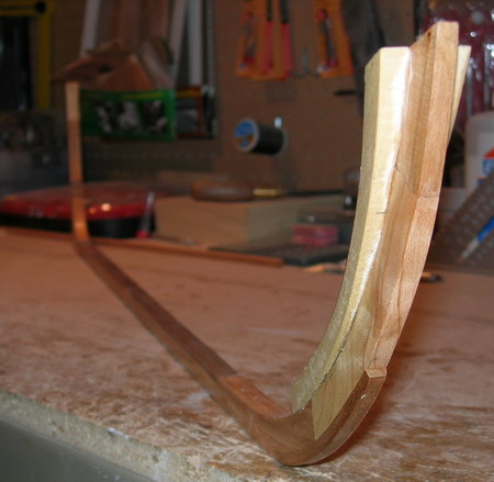
9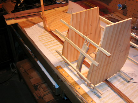
Another view of the start of the framing process. Woods used in framing include Birch, Sycamore, Apple, Walnut, and Alaskan cedar.
10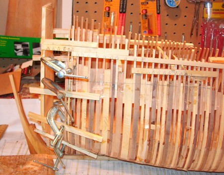
How frames are kept close to the lath. Notice the markings on the lath that are a reference to keep the top timbers in the right position.
11
The framing in later stages...
12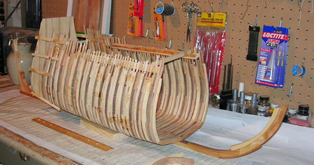
13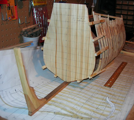
14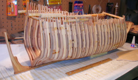
15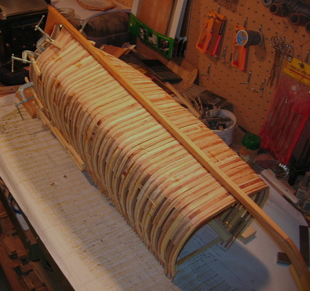
The completed framing with wales installed...
16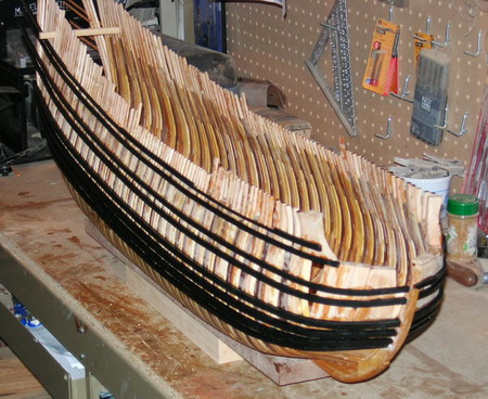
17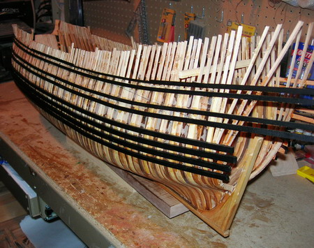
18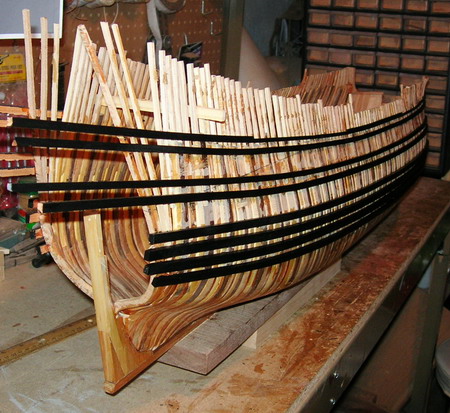
19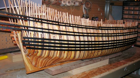
The wales were made of Yew and then painted black after installation. Wales are a critical component in that they help hold any framed up model ship together.
The next step was to build the convex lower transom and to cut out gunports as shown in the pictures below.
20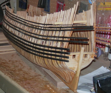
21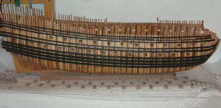
22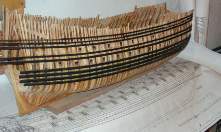
After that was complete it was time to start planking the outside of the ship. The planking in between the wales is made of Walnut.
23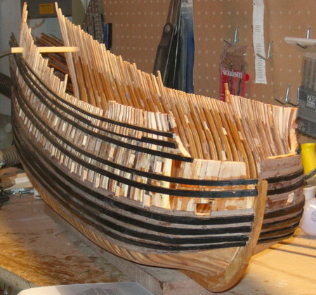
24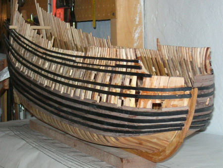
25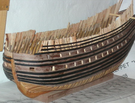
And the completed planking.
26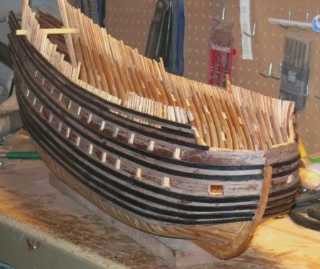
Notice that I left the lower part of the hull un-planked to show the hull framing work.
27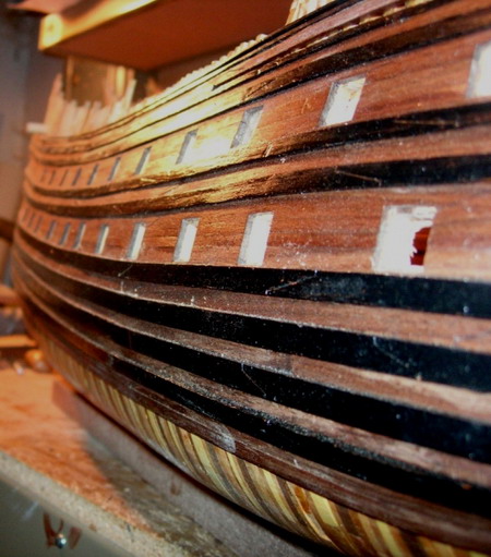
The completed planking with finish applied. Notice the scarph joints in the wales and planking. They are in the same positions as they are in the real ships planking.
Now it was time to start the process of planking the inside of the ship or installing the ceiling. This was done by first putting in the deck clamps, or thick runs of plank that will eventually hold the deck beams up in their proper positions.
All of the inside planking was made in Sycamore.
28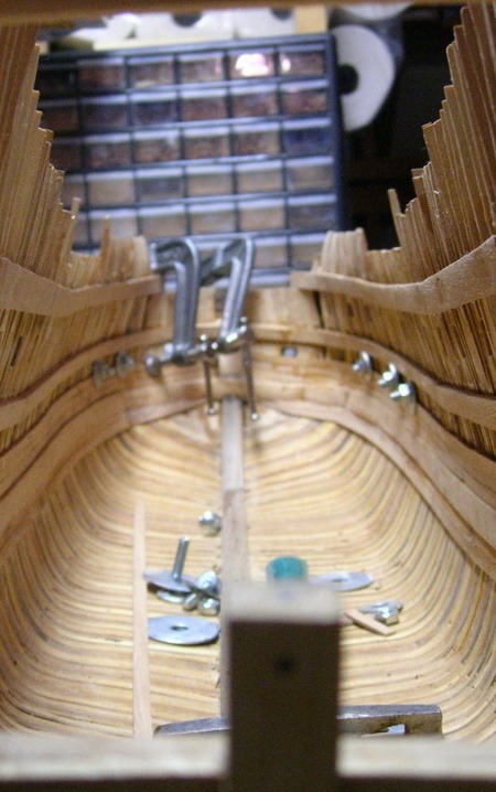
Notice the small carriage bolts. They, together with large washers and nuts, can form wonderful planking clamps.
They simply go through a gunport and when tightened hold planking to the framing very well.
29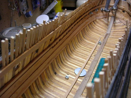
Planking the inside of the bow. Large clamps are critical in this process.
30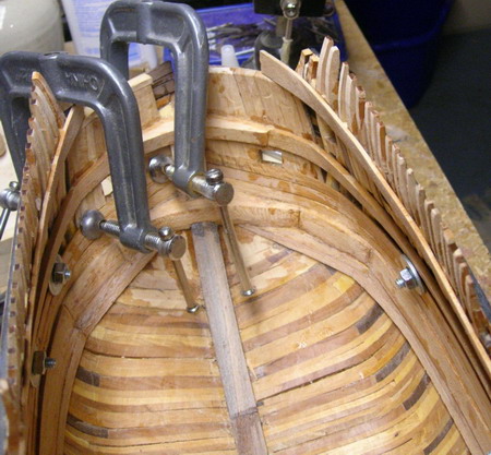
31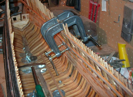
The deeper the throat on the clamp the better!
Finished inside planking.
32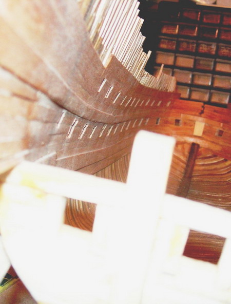
The finished planking, both inside and out….
33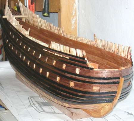
34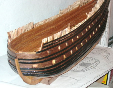
After this was finished and the gunports cut on the inside planking, deck framing could commence. I decided to start with the lower gundeck. I skipped framing the orlop since the viewer would not be able to see any detail on it and only a very little on the lower gundeck.
Before I started, however, I fitted the ship with over 100 amber colored LED lights. The power cord runs out a hole in the keel. I did this because no light will be able to get through the solid wall of wood that is made by the framing. It will also allow the viewer to see more inside detail. LED lights will burn for 20 years straight (over 200,000 hours) and the LED’s in my Wasa may not burn out in my lifetime since I will not have them on all the time.
All of my deck frames were soaked in water for a few days, wrapped in a wet cloth, and then microwaved in order to steam them. They were then placed in a deck frame jig and clamped tight in order for the frames to take on their round up shape.
35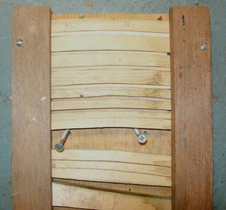
A deck frame jig. Most of my models deck frames were pressed in a larger jig than this, however!
36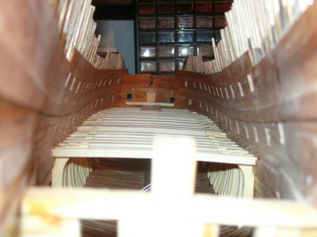
Start of the deck framing on the lower gundeck. Notice the deck frame knees and how they are uneven at their tops. These eventually were trimmed to make way for the waterways.
The knees are made in Alaskan Cedar and the deck frames are made in Basswood.
37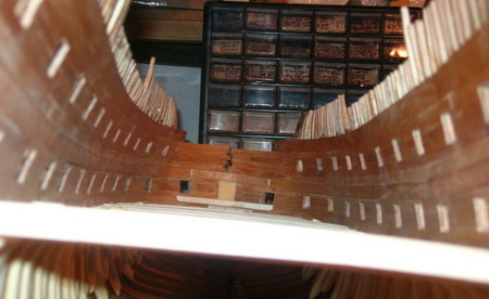
A lower view.
38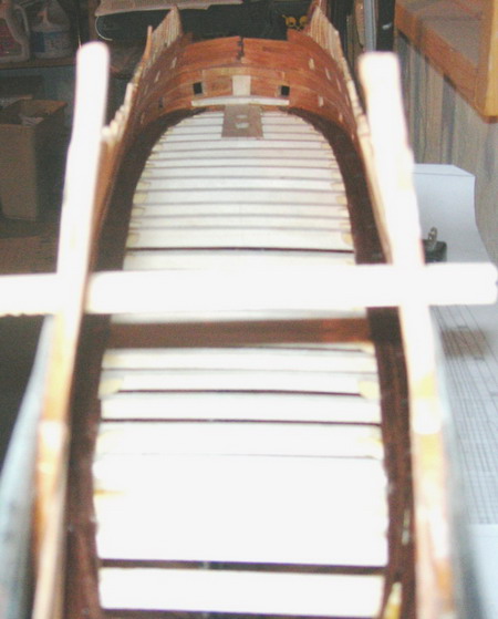
The installation of the waterways, which are made in walnut, along the edges of the deck.
Notice the knees have been trimmed and recessed along with the beams to take the waterways.
39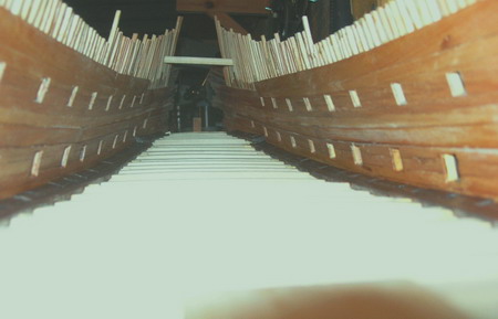
Inside view of the ship facing aft. Notice the upward trend of the deck and the waterways at the edge.
40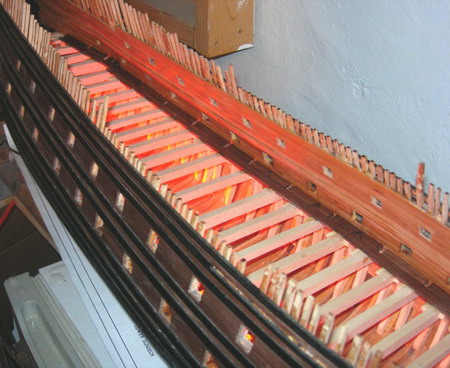
Inside view of the ship with the LED lights turned on. Notice the gaps in the outer waterways. They will be for the knees of the upper gundeck to fit through.
41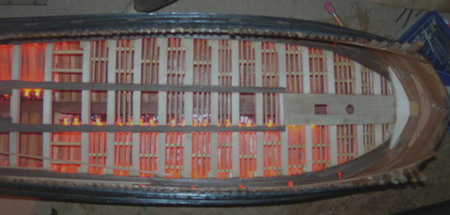
The deck framing with waterways, kingplanks (Walnut), and most of the half beams (Mahogany) and carlings (Alaskan Cedar) installed.
42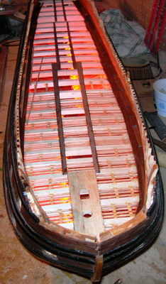
Looking aft.
The next step, after the deck framing was complete, was to start installing what little deck planking that I was going to put in. I decided to only plank as much as was needed for the 24 pound gun carriages to sit on. This was so that light could pass through the deck framing to the upper portions of the model and also to show off all the work that I did in the deck framing itself. The planking, in Walnut, was made to the dimensions of the original planks and below are pictures of the finished deck planking.
43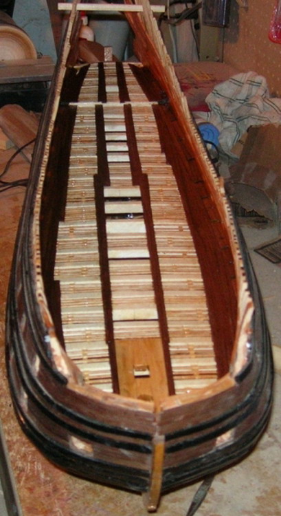
44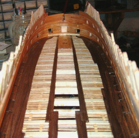
Now it was time for me to make my 24 pound cannon in preparation for their installation on the lower gundeck. I first turned a master out of Dogwood on my lathe and then carved in the ornamentation.
45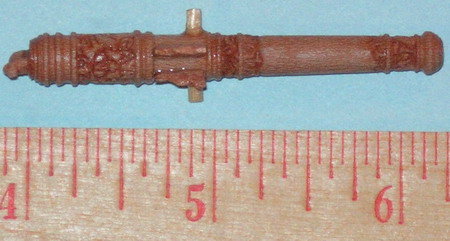
46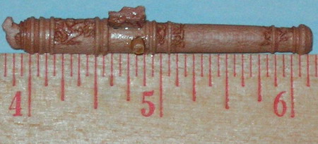
47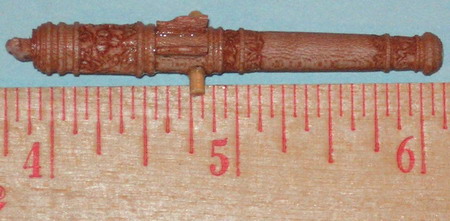
Notice the decoration on the breach. If you look close enough you can see that it says “GARS” and 1626, the Kings initials and the date of casting. All details present on the originals!
I then bought, from micro-mark, some casting supplies that included mold rubber, mold release, casting talc, and a tin-bismuth alloy that melts at 280 degrees F.
Micro Mark also has a very good and inexpensive booklet that tells how to cast small metal parts. I would highly recommend it if you are thinking of trying casting.
Just go there and type “casting” in the search box.
48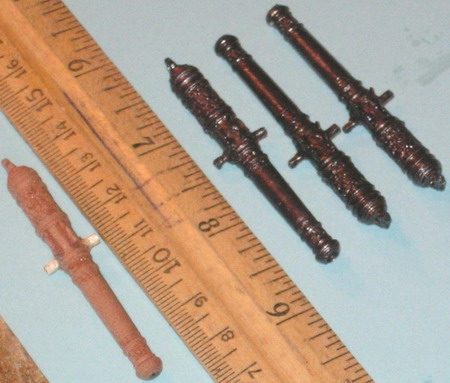
The finished product.
49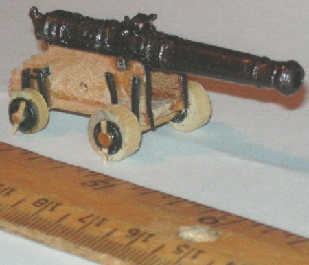
The finished product on its built up carriage. The carriage alone is made up of 30 individual metal and wooden parts. Most of the wooden parts in the carriage are in Birch.
50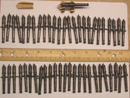
All of the 24 pounders for my Wasa model.
After all of the carriages were made, it was time to install the guns and rig up their tackles.
51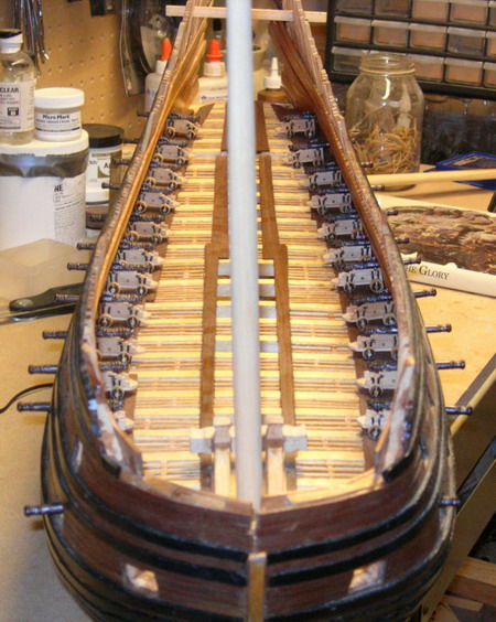
All of the guns on their carriages ready to be rigged.
52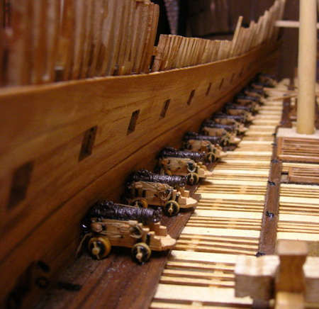
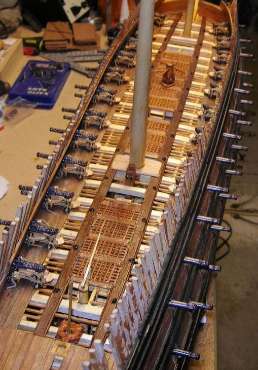
The starboard side battery rigged and ready to fire!
I also, around this time, needed to make the details that go down the middle of the deck. These include.
53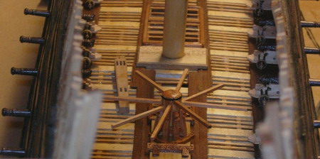
The lower gundeck capstan which is in Apple.
54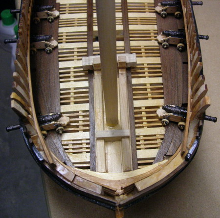
The lower gundeck riding bits (Cherry).
55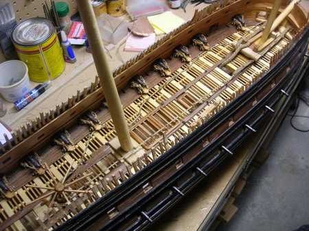
The lower gundeck hatch combings (Apple), anchor cable, messenger rope, and other assorted details.
56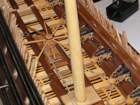
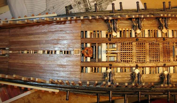
Close up of the details towards the aft part of the lower gundeck.
57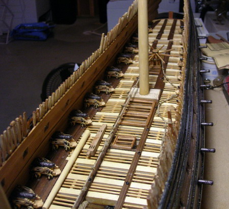
Completely finished lower gundeck.
After the lower gundeck was complete, it was now time to start framing the upper gundeck.
58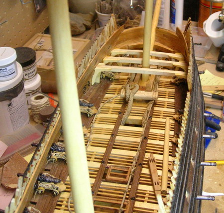
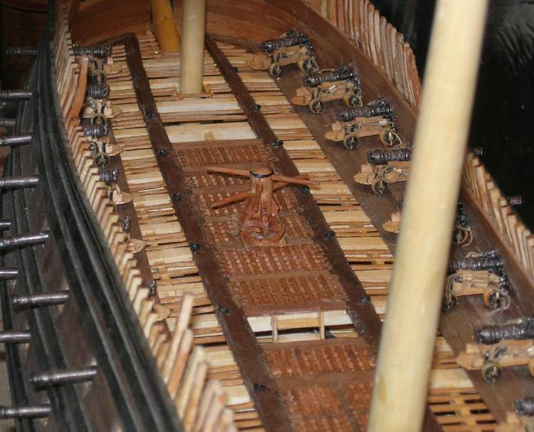
Notice the knees going down through the waterways and how the guns fit between the knees in their natural position.
59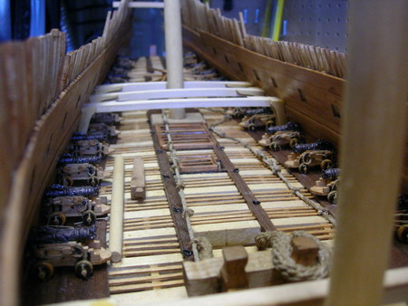
Looking aft.
60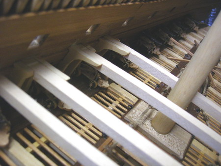
The starboard side. Deck framing for the upper gundeck is made in the same woods as the lower.
61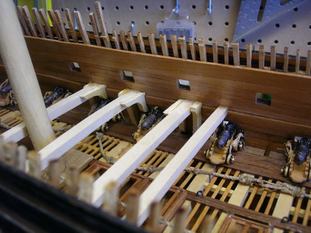
70 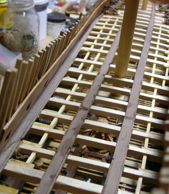
71 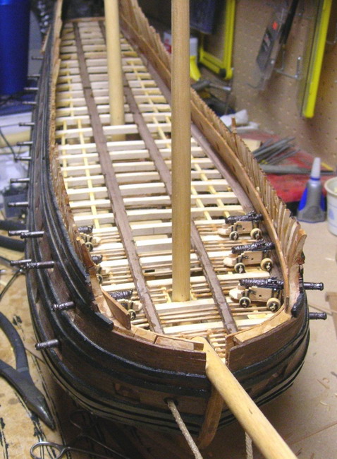
70 and 71 - Upper deck with carlings, kingplanks, waterways, and some half beams installed....
72 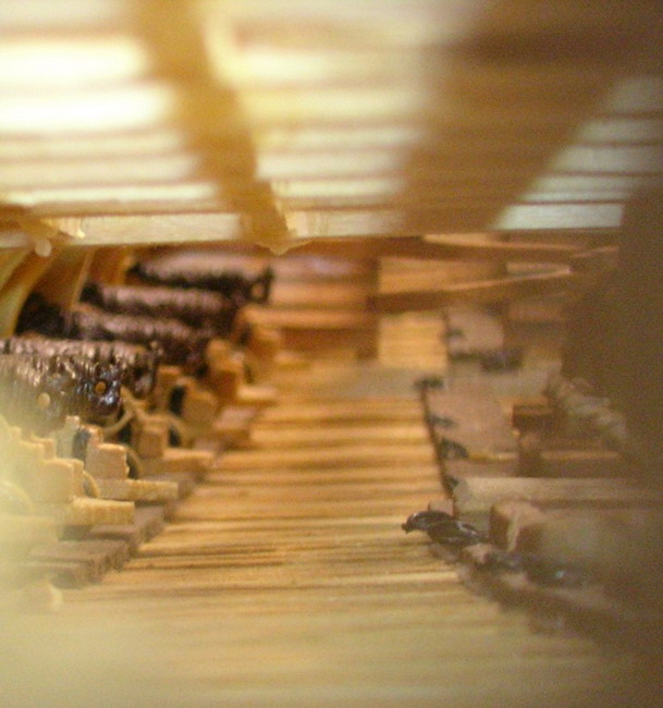
73 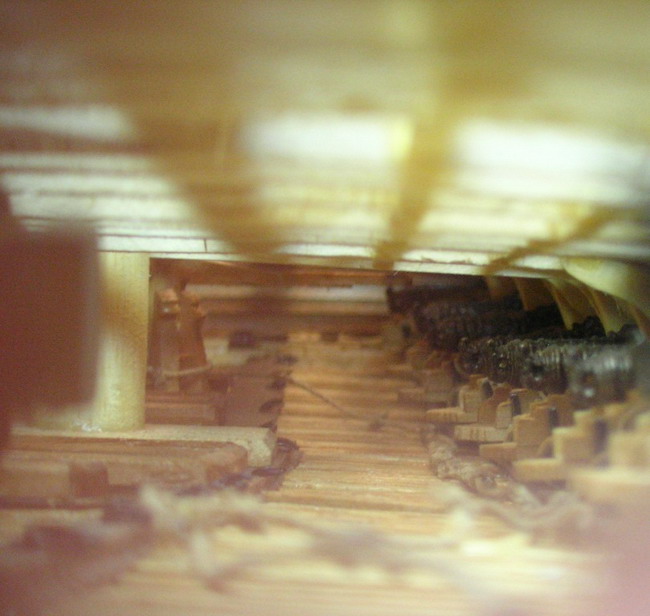
72 and 73 - Looking into the lower gundeck through a gunport…
74 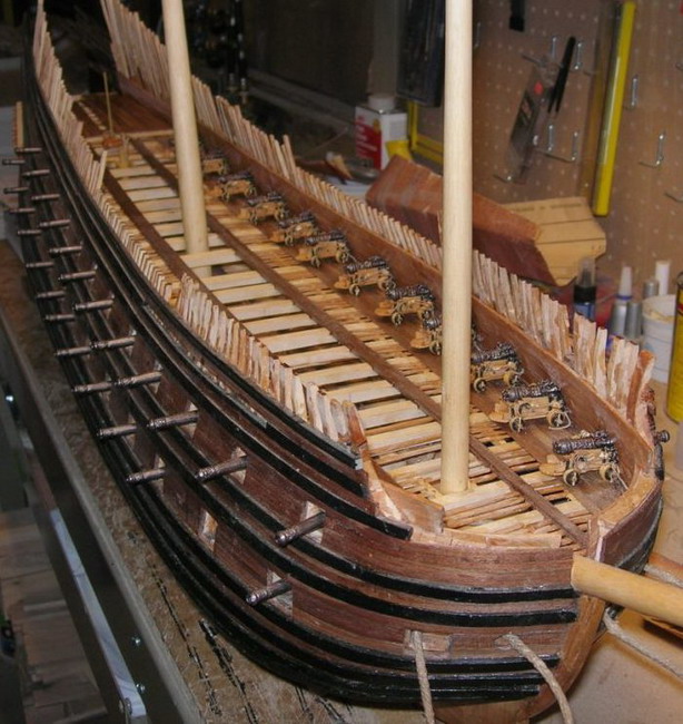
75 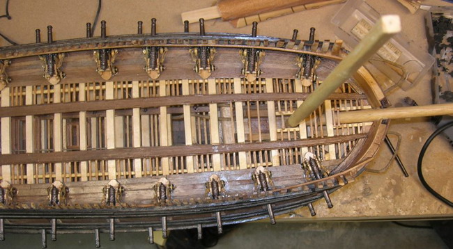
74 and 75 - More progress on the upper gundeck…
76 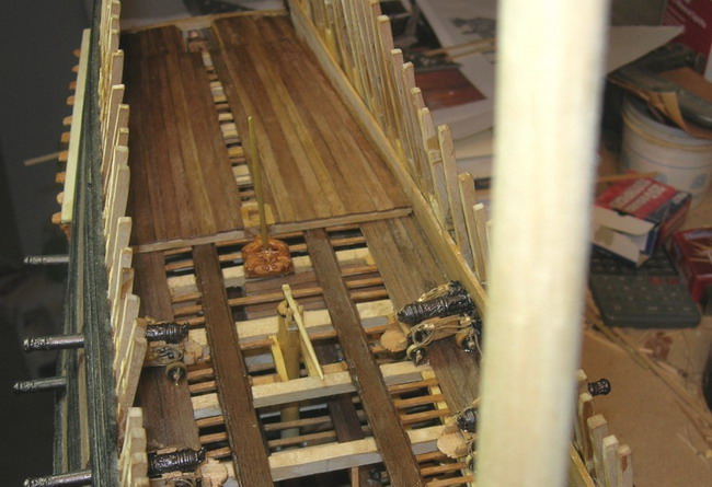
False floor in the admiral’s cabin….
77 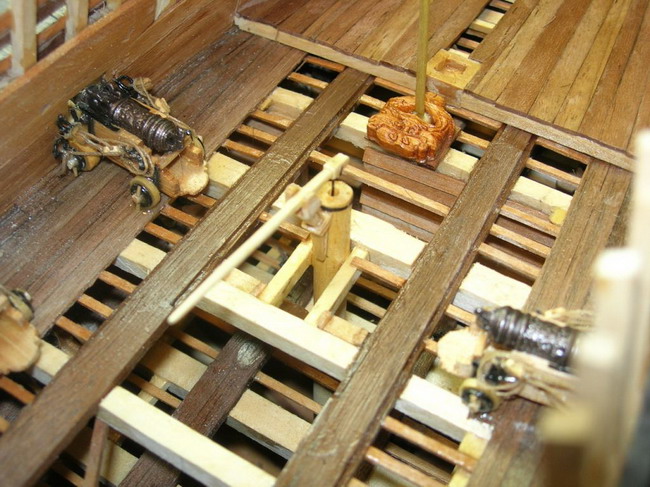
78 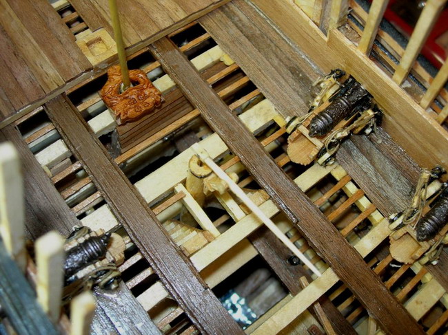
77 and 78 - Whipstaff and alder log pump….
79 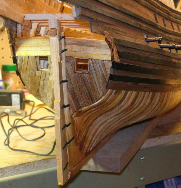
80 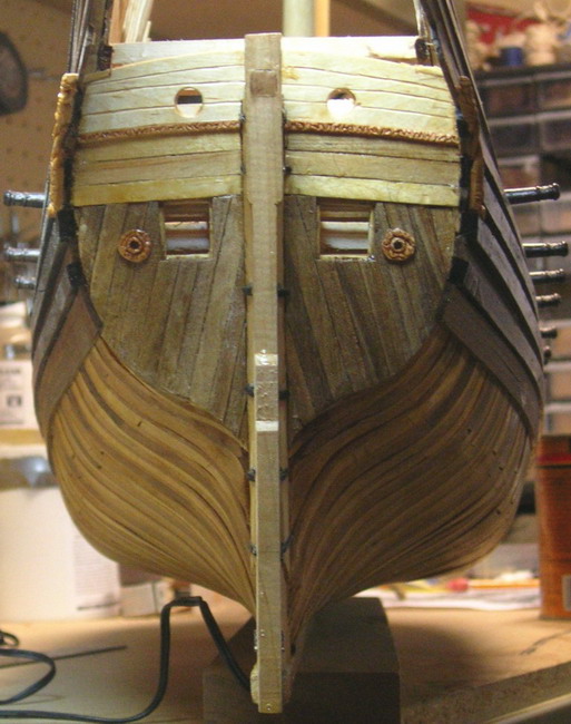
81 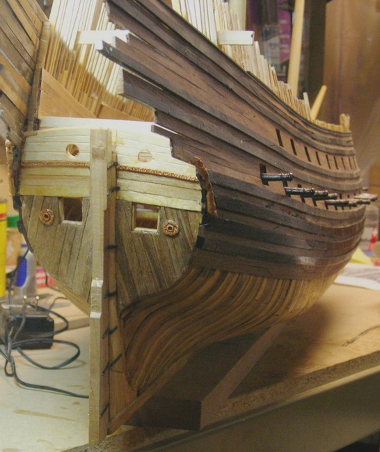
79 à 81 - Work on the lower stern…
82 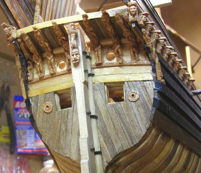
83 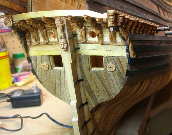
84 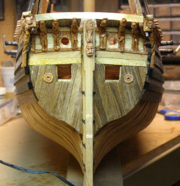
82 à 84 - The beginning of installing sculpture on the stern…
85 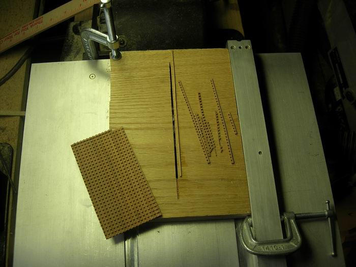
86 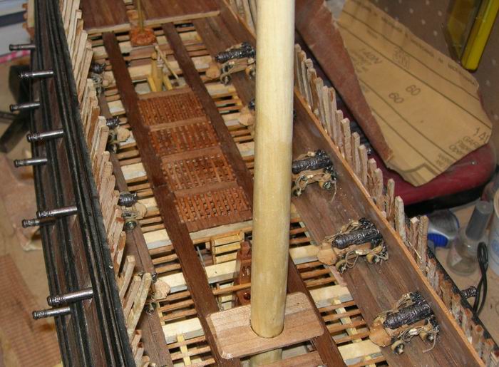
87 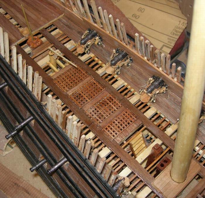
85 to 87 - Gratings cutting and installing.
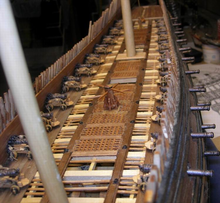
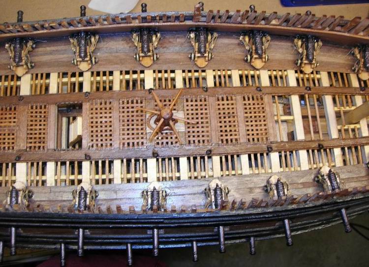
93 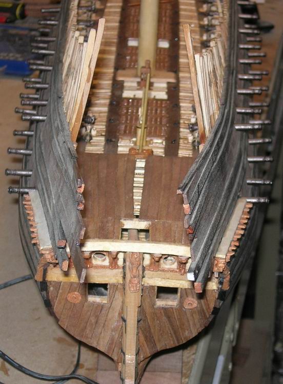
94 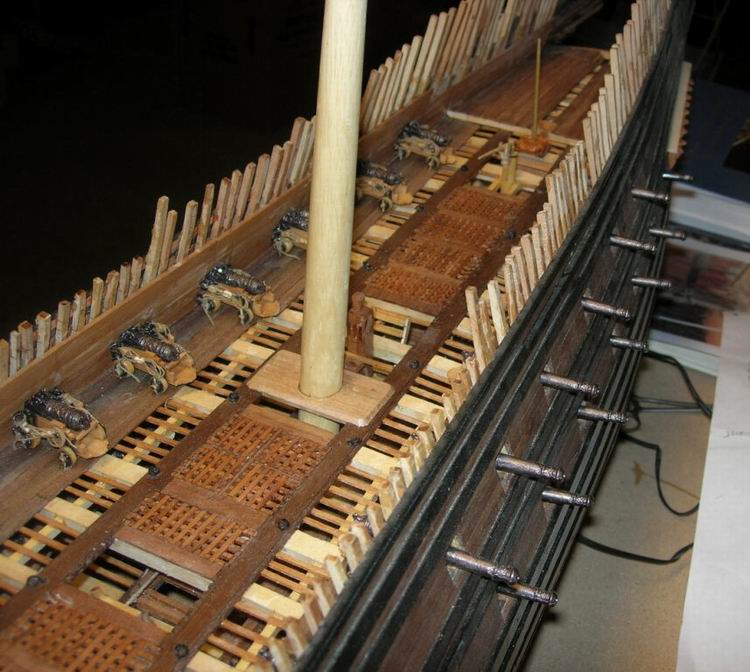
95 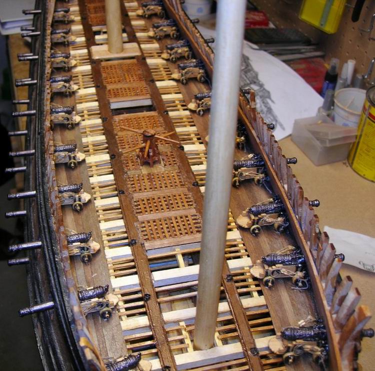
88 à 95 - Finitions du pont supérieur.
That is as far as I have gotten! Check back for more pictures as I progress!
THE SCULPTURE
Wasa was adorned with over 700 carved ornaments. I have made most of these ornaments so far but will not get into how I made them here. You can visit my website in order to learn how to make sculptures for model ships.
http://clayton707.googlepages.com/carvingpracticum
Woods used in my carving include Dogwood, Holly, Swiss Pear, Apple, Yew, Walnut, and a very small amount of Birch.
62 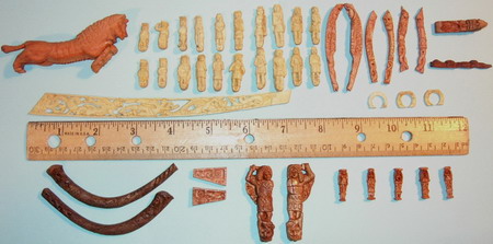
The beakhead sculptures.
63 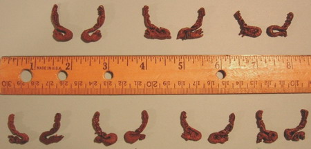
Railing links
64 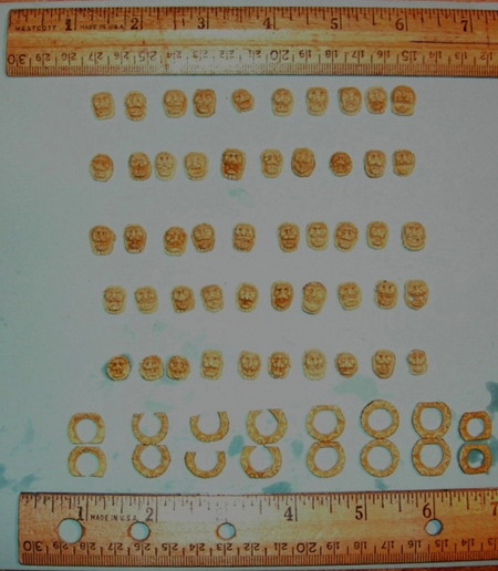
Gunport lion masks and wreaths
65 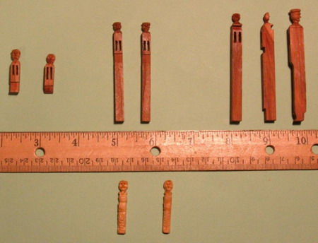
Knightheads and tackblocks.
66 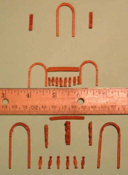
Exterior bulkhead carvings
67 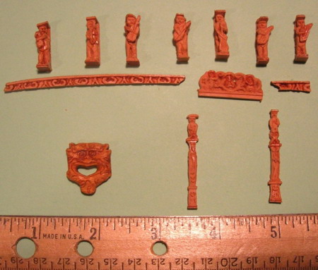
Helmsman’s cabin carvings
68 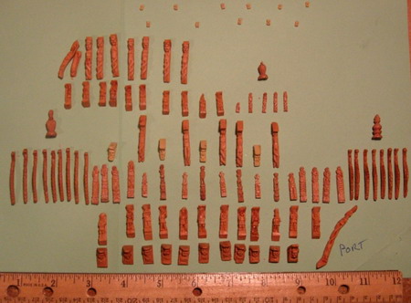
Port quarter gallery carvings
69 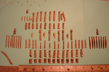
Starboard quarter gallery carvings
THE END!
A special thanks to Fred Hocker, Director of Research at Vasamuseet and to Herve Sasso for making my Wasa model and this report possible.
http://clayton707.googlepages.com
Any questions or comments contact me at :
Check back often because this report will be updated with my future progress!